MD Series Microdosers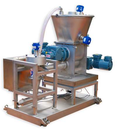
Construction specifications
The new technological design of MDS microdosers gives significant improvements in performance compared to the old style.
All the parts in contact with the product are made of stainless steel or non-stick material.
The body of the MDS microdoser is made from a single cast from materials which allow the powder to move freely in the chamber with the vibrations produced by the operation of the machine itself.
The chamber can be made of various materials according to the use of the powder to be processed.
The capacity can be varied with a frequency variator or inverter.
The dosing elements can be replaced individually, and exchanged for different tools.
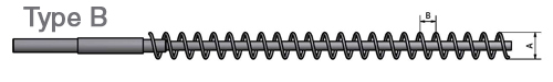
Where the product has a tendency to become compressed, the standard dosing tool can be changed, replacing the continual spiral (type A) with a memory wire spring (type B), to avoid compacting the material between the spirals.
Dosing principles
The constant-speed screw feeder has a volumetric capacity calculated by the volume of material in the section of one complete spiral and the diameter of the screw, so the dosage varies with the number of spirals.
With most dosers on the market the margin of error is around 4%. The variables are mainly from the filling of the hopper, technically known as the fill factor.
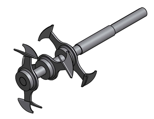
The agitator reel located up-line from the dosing screw feed, as well as breaking up clumps and crusts formed in the silo, makes the material more fluid, resulting in even pressure and weight on the spiral screw.
The variation in weight for our dosers is around 2%, representing a significant factor in the quality and continuity of dosing.
The dosing capacity also varies with the physical and chemical properties of the product: materials which are identical from a chemical point of view may show variations in weight and dosage capacity if they are not equivalent in granulation or other physical parameters, and thus cause variation in dosed quantity with the same rotation speed.
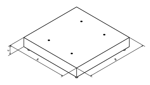
Gravity weighing scale for product dosage
The scale ensures that the dosage ratio is perfectly in line with the desired value. It is located underneath the body of the doser unit, and weighs the product feeder as well as the product itself inside the storage hopper.
The scale, with programmable timer for readings, weighs the material and calculates how much weight has been lost in kilos over the set time.
It then calculates the dosage as an hourly figure and checks that this figure corresponds to the value set by the operator or the control room, thus guaranteeing effective weight control in the short and long term.
Checks are carried out at random intervals by the instruments in the load cell.
If the calculated weight is lower than the set value by a margin greater than 4%, the apparatus emits an alarm signal warning of the failure to reach the required weight / dosage; in this case the operator will intervene to inspect the problem.
Brochure
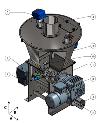
Machines details
 |
| Position |
Description |
| 1 |
FEEDER BODY |
| 2 |
HOPPER TO 58 dm3 |
| 3 |
SLEEVE FEED |
| 4 |
PIPE |
| 5 |
SCREW |
| 6 |
LEVEL SENSOR |
| 7 |
FEEDER GEARMOTOR |
| 8 |
AGITATOR GEARMOTOR |
| 9 |
BALL VIBRATOR |
| 10 |
AGITATOR GROUP |
|
| Dimensions |
| Size |
A |
B |
C |
D |
| 50 |
880÷1550 |
854 |
1051 |
65 |
| 60 |
880÷1550 |
854 |
1051 |
76,1 |
| 70 |
880÷1550 |
854 |
1051 |
88,9 |
| 80 |
880÷1550 |
854 |
1051 |
101,6 |
| 100 |
880÷1550 |
854 |
1051 |
114,3 |
|
| Dimensions ATEX |
| Size |
A |
B |
C |
D |
| 50 |
880÷1550 |
854 |
1051 |
76,1 |
| 60 |
880÷1550 |
854 |
1051 |
88,9 |
|
Micro-dosage system ideal for depuration with Activated Carbon and/or Lime  , fully compliant with ATEX legislation. , fully compliant with ATEX legislation.
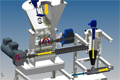
This dosage system is an automated turnkey installation which uses compressed air to transport the product to the point of injection. With minimum air pressure of 1-3 bars, we manage to convey reasonable quantities of product over notable distances. The Venturi-effect ejector gives excellent performance, with significant results in terms of power output and functionality.
|
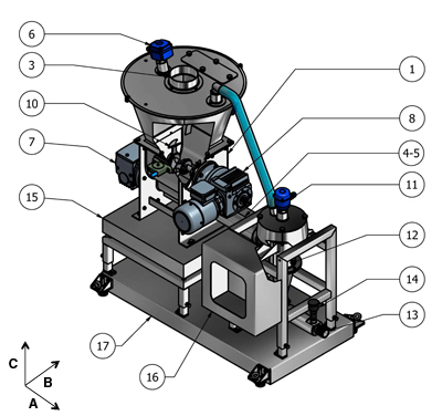 |
| Position |
Description |
| 1 |
FEEDER BODY |
| 2 |
HOPPER TO 58 dm3 |
| 3 |
SLEEVE FEED |
| 4 |
PIPE |
| 5 |
SCREW |
| 6 |
LEVEL SENSOR |
| 7 |
FEEDER GEARMOTOR |
| 8 |
AGITATOR GEARMOTOR |
| 9 |
BALL VIBRATOR |
| 10 |
AGITATOR GROUP |
| 11 |
LEVEL SENSOR VIBRATION |
| 12 |
BARREL OF PROPULSION |
| 13 |
EJECTOR |
| 14 |
PRESSURE TRANSMITTER |
| 15 |
WEIGHING SYSTEM |
| 16 |
PNEUMATIC PANEL |
| 17 |
PLATFORM |
|
| Dimensions |
| Size |
A |
B |
C |
D |
| 50 |
1492 |
872 |
1475 |
65 |
| 60 |
1492 |
872 |
1475 |
76,1 |
| 70 |
1492 |
872 |
1475 |
88,9 |
|
| Dimensions |
| Size |
A |
B |
C |
D |
| 80 |
1492 |
872 |
1475 |
101,6 |
| 100 |
1492 |
872 |
1475 |
114,3 |
|
Micro-dosage system ideal for depuration with Activated Carbon and/or Lime , fully compliant with ATEX legislation.
This dosage system is an automated turnkey installation which uses a blowing pump to transport material through the tubes. This system allows noteworthy quantities of material to be propelled, and also has a crossflow star valve which enables the pressurized tube circuit to be isolated.
|
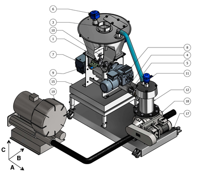 |
| Position |
Description |
| 1 |
FEEDER BODY |
| 2 |
HOPPER TO 58 dm3 |
| 3 |
SLEEVE FEED |
| 4 |
PIPE |
| 5 |
SCREW |
| 6 |
LEVEL SENSOR |
| 7 |
FEEDER GEARMOTOR |
| 8 |
AGITATOR GEARMOTOR |
| 9 |
BALL VIBRATOR |
| 10 |
AGITATOR GROUP |
| 11 |
LEVEL SENSOR VIBRATION |
| 12 |
BARREL OF PROPULSION |
| 15 |
WEIGHING SYSTEM |
| 17 |
PLATFORM |
| 18 |
FLOW VALVE CROSSED |
| 19 |
CENTRIFUGAL PUMP |
| 20 |
PIPE OF TRANSPORT |
|
| Dimensions |
| Size |
A |
B |
C |
D |
| 50 |
1595 |
872 |
1475 |
65 |
| 60 |
1595 |
872 |
1475 |
76,1 |
| 70 |
1595 |
872 |
1475 |
88,9 |
|
| Dimensions |
| Size |
A |
B |
C |
D |
| 80 |
1595 |
872 |
1475 |
101,6 |
| 100 |
1595 |
872 |
1475 |
114,3 |
|
Micro-dosage system ideal for depuration with Activated Carbon and/or Lime , fully compliant with ATEX legislation.
This dosage system with double microdoser is an excellent piece of equipment for multiple injection lines, which have several pollutant reduction filters and therefore need to optimize the machinery installed for depuration.
The two microdosers positioned on a single base can function independently, both for switching on and off, and for the correct introduction of reagent in the quantities required by data analysis of pollutants in the vapour outlet flue.
|
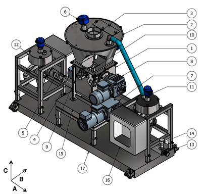 |
| Position |
Description |
| 1 |
FEEDER BODY |
| 2 |
HOPPER TO 58 dm3 |
| 3 |
SLEEVE FEED |
| 4 |
PIPE |
| 5 |
SCREW |
| 6 |
LEVEL SENSOR |
| 7 |
FEEDER GEARMOTOR |
| 8 |
AGITATOR GEARMOTOR |
| 9 |
BALL VIBRATOR |
| 10 |
AGITATOR GROUP |
| 11 |
LEVEL SENSOR VIBRATION |
| 12 |
BARREL OF PROPULSION |
| 13 |
EJECTOR |
| 14 |
PRESSURE TRANSMITTER |
| 15 |
WEIGHING SYSTEM |
| 16 |
PNEUMATIC PANEL |
| 17 |
PLATFORM |
|
| Dimensions |
| Size |
A |
B |
C |
D |
| 50 |
2140 |
1126 |
1485 |
65 |
| 60 |
2140 |
1126 |
1485 |
76,1 |
| 70 |
2140 |
1126 |
1485 |
88,9 |
|
| Dimensions |
| Size |
A |
B |
C |
D |
| 80 |
2140 |
1126 |
1485 |
101,6 |
| 100 |
2140 |
1126 |
1485 |
114,3 |
|
| POSITION 5 - SCREW |
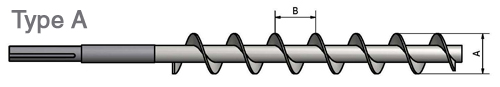
 |
| Size |
Type A |
Type B |
| A |
B |
Vol. step
dm3 |
A |
B |
Vol. step
dm3 |
| 50 |
50 |
50 |
0,082 |
50 |
29 |
- |
| 60 |
60 |
60 |
0,16 |
60 |
35 |
- |
| 70 |
70 |
70 |
0,21 |
|
|
|
| 80 |
80 |
80 |
0,33 |
|
|
|
| 100 |
100 |
100 |
0,7 |
|
|
|
| POSITION 10 - AGITATOR GROUP |
|
| POSITION 15 - WEIGHING SYSTEM |
|
| A |
B |
C |
N. load cells |
Capacity Kg |
Weight transmitter |
Vers. ATEX |
| 600 |
600 |
100 |
4 |
300 |
DAT400 |
Yes |
| 600 |
600 |
100 |
4 |
400 |
DAT400 |
Yes |
|
Gallery


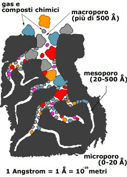 Activated carbon in powdered form is used to reduce emissions of heavy metals, furans, dioxins etc, but its dosage is problematic, mainly because it does not flow smoothly; similarly, lime, used for the reduction of pollutant acid emissions, displays the same dosage problems.